This is without a doubt the most ambitious mechanical project I’ve ever taken on. I’ve dabbled in electronics since I was a kid and I’ve been doing embedded systems programming since middle school, but until I started this project, I’d never made anything with a motor that wasn’t part of a Lego or Erector set.
If you aren’t familiar with Burning Man, the motivation for the project probably needs some explanation. For that matter, Burning Man itself needs some explanation. The documentary Spark: A Burning Man Story is a good place to start.
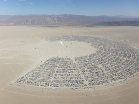
The event is held on a dry lake bed that’s dusty, flat, and big. You get around mostly on foot and by bicycle, and the only motorized vehicles allowed are heavily-modified ‘mutant vehicles‘, usually referred to as art cars. Mutant vehicles are allowed only by invitation of the Department of Mutant Vehicles, which imposes ever-tougher licensing requirements for both day and night use. The short version is that it can’t look like a regular vehicle, and it must be radically illuminated at night.
I started thinking seriously about building an art car after my 2015 burn. My knees were giving me a lot of trouble and my camp’s placement was half a mile from the Esplanade, which really limited how much I was able to do and see that year.
I’m also an introvert. I’m not anti-social and in fact I have a great time meeting tons of people out there every year, but it’s usually while I’m doing things like tending bar, serving liquid nitrogen ice cream, or walking around with a giant LED hula hoop, and the constant stream of brief interactions is draining. I have trouble hearing people in noisy environments, too, which makes the bar in particular a difficult place for me at times.
I decided that the way to deal with both the physical and social strain would be to make a vehicle that could get me around, carry a few people at a time, and would be quiet enough that I could carry on a conversation with other riders. I eventually settled on the idea of a motorized couch.
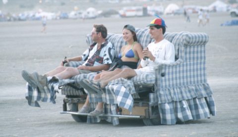
I knew I was at least 20 years late to be the first one to think of that, but it didn’t need to be entirely novel, just fun. What I didn’t realize was just how many furniture cars are already licensed each year. Before I’d gotten properly started the DMV announced that they were limiting certain over-represented categories, including furniture cars, mobile bars, and angler fish. (Bars are obvious, but I’m not sure where the popularity of angler fish cars comes from. The longest art car ride I’d ever had was in fact on an angler fish bar.)
So I set the project aside for a year or so and didn’t really think about it again until the 2017 submission deadline came along in April. I started with a list of requirements:
- Quiet
- Room for 3-4 people
- Mechanically simple
- Something to use lots of scrap hoop LEDs
- Feasible as a solo project
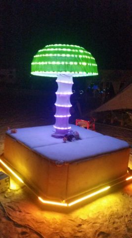
We’ve always got piles of surplus hula hoop tubing and a big box of questionable LEDs salvaged from repairs and warranty replacements, and that led to me to the idea of a big mushroom sculpture. The cap and stem could both be made of various sizes of LED hoops, and more LEDs could be run around the base of the vehicle.
A friend had agreed to help me with the concept sketches for the application process, but something came up at the last minute and she wasn’t available. I’m horrible at sketching so I decided to give it a shot in CAD. I spent a couple of hours working in Alibre Design and came up with something far better looking than I could have managed freehand.
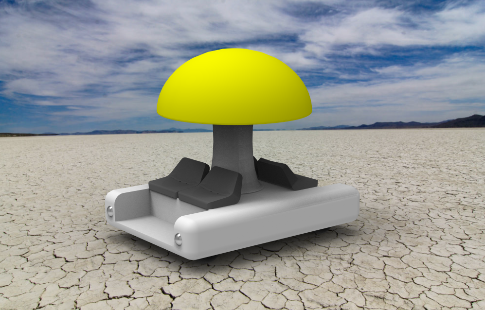
The concept drawing issue also illustrates some of the reasons I chose for this to be a solo project. It’s tough coordinating with friends that mostly live in other towns (I’d live closer but affordable commercial space is scarce) and I had only a rough idea where I was going with the project – not enough to effectively delegate tasks.
What I do have is a fairly well-equipped shop space with lots of tools and plenty of room to work on projects. The shop is equipped with a relatively small set of tools that are used in day-to-day production, a larger and more diverse set used mostly for prototyping and development, and an even larger collection of tools for maintenance and repairs of the equipment and the shop itself. I’d never have imagined that a career in embedded systems programming would require owning a rotary hammer, but that’s one of many tools I’ve acquired since moving the business out of my spare bedroom almost a decade ago.
It’s not an auto shop, though, and over the course of the project I’d have to pick up some basics like a floor jack and a set of jack stands, but nothing major.
Most small art cars are built on golf carts, or occasionally ATVs or scooters. Most of them are gas powered, though there are some notable exceptions like the Acme Muffineering muffin cars. If I’d had the toadstool in mind from the start I’d probably have used a golf cart like a sane person, but thanks to my false start with the couch, I’d already decided I was going to built it from scratch.
The first thing I did when starting on the design was to skim through a copy of Making Things Move by Dustyn Roberts I’d had on my shelf for years. I refreshed my memory on some basic high school physics and read up on some common mechanisms. I spent many hours searching for similar projects, and found some good resources on DIY Go Karts, Argo 6×6 ATVs, and robots.
A chain drive seemed like the way to go. Roller chains give you flexibility in where you place your components, they make 4-wheel drive easier than with a direct drive, they transmit power efficiently, and they handle dust better than belts.
I started the build with some motor experiments. During the couch phase of the project I’d decided to use a 36 volt system because that’s what my forklift uses. I already had the forklift battery to test with, and I had a spare 36 volt charger. Or at least, it was a spare charger before some tweaker broke in and stole the good one, but that’s a story for another post.
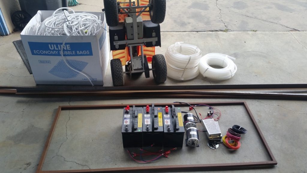
800 watts was about the highest power rating I could find on a 36 volt brushed DC motor, so I’d purchased two Unite MY1020 800w scooter motors and some cheap motor controllers from China. I’d also found a small electric ATV locally when I realized that buying it would be cheaper than buying four wheels separately. This is what I had set aside for the project when I submitted the application:
Those motor controllers didn’t survive the first round of bench tests. I accidentally flipped the direction switch on one from forward to reverse at full speed and the motor jumped right off the table, did a 360, and landed back on its mount. The controller, meanwhile, developed a new smell of burnt electronics. The other one never seemed to work right at all.
I gave up on those and ordered an MCP236 from Ion Motion Control in Temecula.
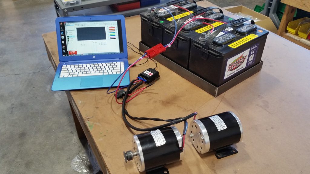
It’s rated at 30 amps per channel and could supposedly handle much larger surges. The motors were rated for a continuous current of about 27 amps each. That wasn’t a lot of margin but I figured they’d only be drawing anything close to their maximum for short periods and it might be OK. I fired them up and checked everything out with no load using the IonStudio software supplied with the controller, and everything worked fine.
The MCP controllers are cool little gadgets with a ton of features – not all of them very well documented, but Ion’s email support was good. Being an embedded systems programmer I’d of course expected at the start to have a custom microcontroller-based control system of some sort, but the MCP controllers have enough features that I didn’t really need to add any of my own electronics to make it do what I needed it to. I found a FlySky transmitter and receiver pair, intended for R/C helicopters and airplanes, on Amazon for about $50 and was able to connect it directly to the MCP controller, though a minor firmware fix was needed on Ion’s side.
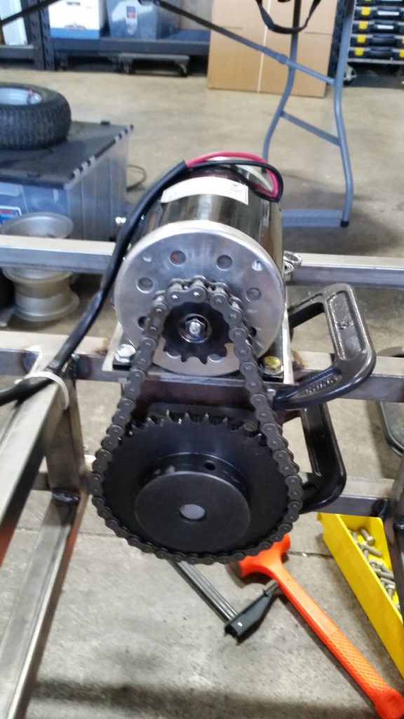
Finding sprockets for the motors turned out to be more difficult than expected. They have an uncommon metric shaft type and came with sprockets suitable for #25 chain, which looked way too small for this application – significantly smaller than bicycle chain. I upgraded to #35 and that was still too small, and I finally settled on #40, but couldn’t find a #40 sprocket that would fit the shaft.
The lack of compatible parts told me I was probably doing something wrong or misunderstanding something important, but I wasn’t sure what. The easiest way to find out what I was doing wrong was to keep going and see what broke, so I just welded a sprocket with the right teeth onto one with the right bore, and built a small test rig to try it out.
It seemed to work with my small-scale bench test, so I turned my attention to the chassis. The decision to use 1″ x 1″ hollow square steel tubing mostly came down to the fact that I already had hundreds of feet of it on hand. The local steel yard has decent prices and free delivery, so I’d stocked up for making racks and fixtures. Having a warehouse and a forklift definitely makes some of this stuff easier; if I’d had to buy the steel in 6-foot lengths at the hardware store, it would have cost me at least six times as much.
The model above taught me a couple of things about how to position and attach mounted bearings. I made some tweaks and started designing the chassis in Alibre.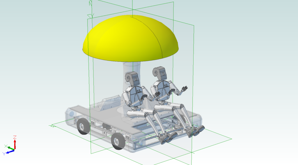
I’d originally planned to have the wheels located within the frame. It’d make the sides flat and easier to attach stuff to and reduce the chances of bending an axle, but I decided against it because changing a tire would then require removing an entire axle.
I’d also discovered when I added human figures to the model that the seats would need to be wider, and those two changes made the final vehicle quite a bit wider than I’d originally expected. In retrospect, neither was strictly necessary. Removing an axle isn’t hard, and since I eventually eliminated the seats entirely, crowding was never an issue.
I tinkered with parts and worked on the CAD model through mid-June but hadn’t started an actual assembly. The second half of the month was taken up by my daughter’s high school graduation and our move to a new place.
My son had already been out of the house and living on his own for a couple of years, and with proximity to school no longer an issue, I decided to move to a smaller, lower-maintenance place close to the shop. By the start of July we’d finished the move and my daughter had gone off to Arizona to spend a few months with her mother, and I found myself in the position of having an empty nest (at least temporarily) at age 40. I’m still trying to get used to the idea.
With greatly reduced obligations at home and only a 3-minute commute, I started spending a lot more hours in the shop. Toward the end of the project I was working so many early mornings and late nights that my neighbor thought I’d moved because he hadn’t seen my car in weeks.
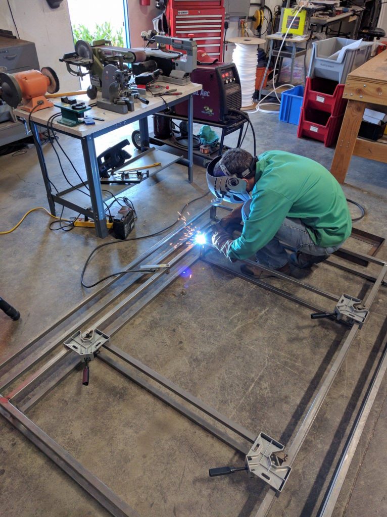
I still didn’t have anything close to a finished design but I knew that I needed to get something physical built on the actual car. Analysis paralysis has been the death of too many of my projects, so I took what I had and on July 2, with 53 days until departure, I started welding.
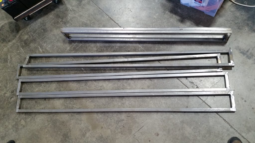
I welded a bunch of rectangular frame sections, and then welded those together.
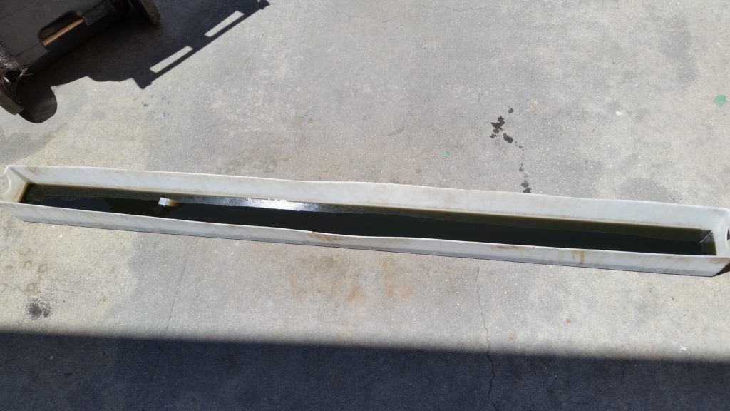
So far, so good. The steel had been outside for a couple of years and in a spot not as protected from the elements as I’d hoped, so it was pretty rusty. I discovered Evapo-Rust and used a lot of it, with good results. My travel trailer has a 7′ long HDPE trough in a pass-through compartment that made a perfect container for soaking the steel.
You can really never have too many welding clamps. I already had four of these corner clamps and I added many more C-clamps, quick release clamps, and vise grips to my collection. I’m fairly certain that I did more welding on this project than on all of my previous welding projects combined.
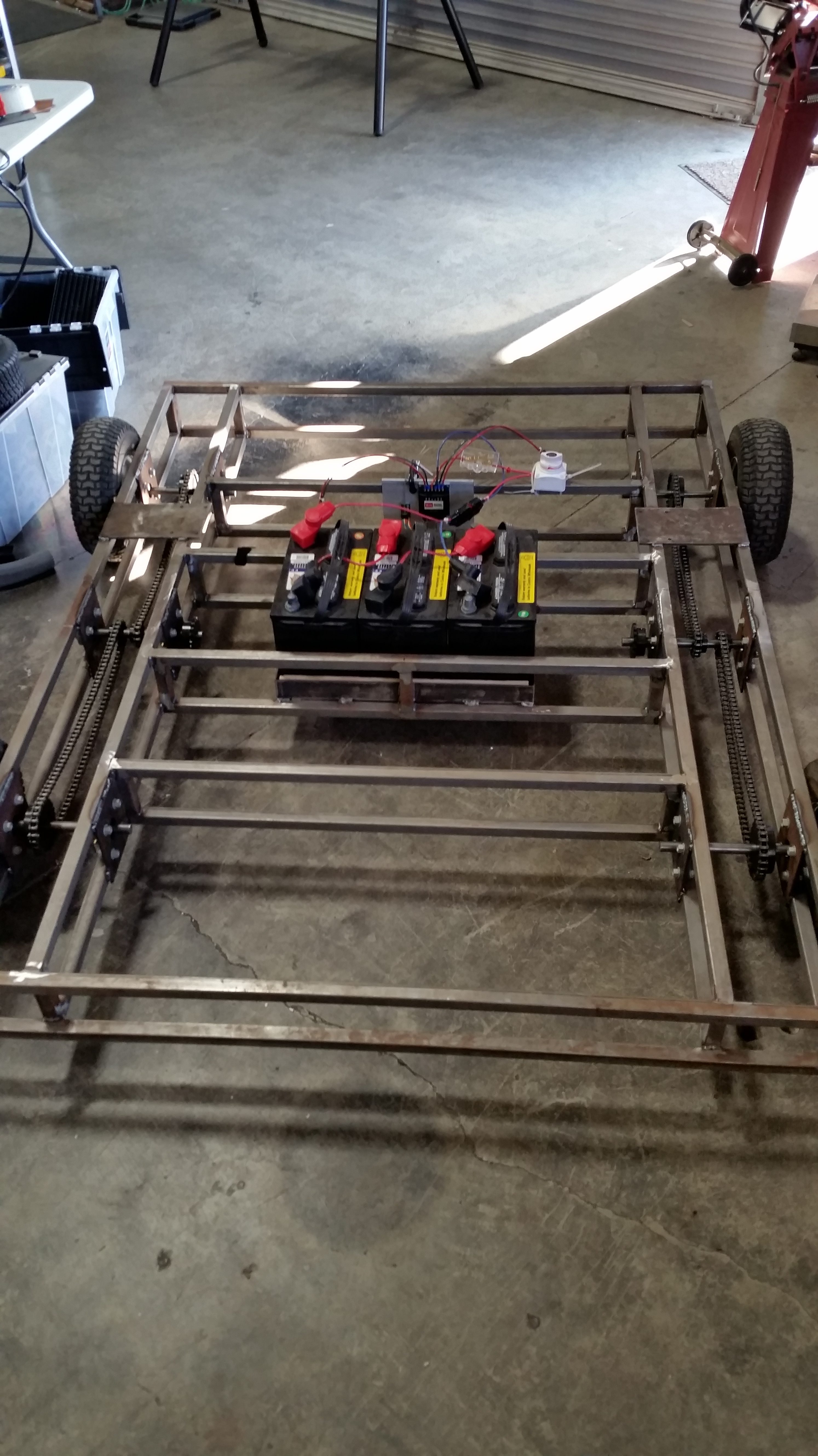
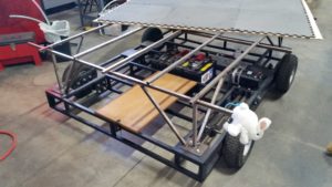
I’d picked sealed lead acid batteries – standard 12v marine deep cycle types – because they’re cheap, rugged, and readily available at the local Costco. They are not lightweight. I knew the three batteries together would weigh close to 160 pounds, and I was afraid that they’d cause the frame to sag. Turns out I’m really bad at estimating the strength of steel structures.
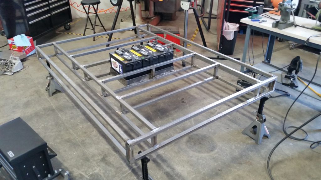
The combined weight of the batteries and me on the very center of the frame caused it to bend less than I could measure with a ruler – certainly not more than 1/8″. The chassis was much stiffer than I’d expected, even before adding any bracing.
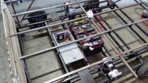
By July 8 I had the batteries and motors mounted and was able to test the motors on the frame.
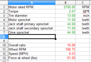
They whirred away just fine. My concerns at this point were with their cooling (they have no fans and nothing much to remove heat) and the reduction ratio required. I’d need to somehow get from 2700 RPM at the motor shafts to around 150 RPM at the wheels.
I’d done my initial calculations for the couch project assuming #25 chain. The sprockets for #25 are much smaller (and less expensive!) than for #40. The sprockets I’d need to get the required reduction in two stages (motor to jackshaft, jackshaft to axle) would have required gigantic sprockets that would have left almost no clearance between the chain and the ground. I’d have to use three stages to get a 16:1 reduction ratio.
I had a design in mind, but initial testing did not go well. This was my test setup for the first reduction stage:
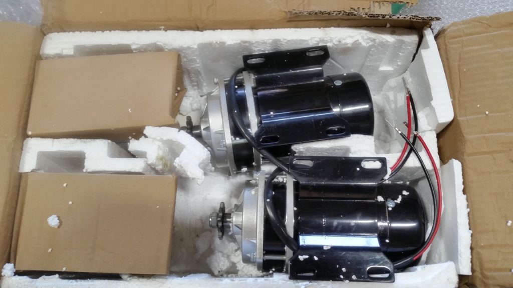
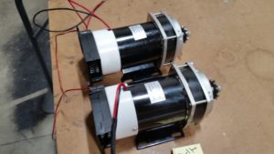
Probably because of my improvised sprocket attachment, it had a horrendous vibration before it even got up to 50% of full speed. There were now 42 days remaining and I decided the motors were just not going to be suitable. After much searching and many dead ends with domestic suppliers, I ordered two MY1020ZX Dayton gear motors from Motion Dynamics in Australia.
These are essentially the same motors but with a shaft-driven cooling fan and a 6:1 planetary gear box. Keeping the highest-speed parts sealed up in the gear box greatly simplified the rest of the drive train. At under USD $120 each the motors are reasonably priced, but shipping was expensive. I’d love to be able to get motors like this a little closer to home, but I haven’t found a source yet.
These motors also came with larger sprockets, specifically #420 size. This solved one of my problems and answered a question about what I was doing wrong before. I’d mistakenly thought that #420 was a metric size designation, or at least not related to the ANSI #25, #35, and #40 chains I’d used. Turns out it’s just narrower than #40 but has the same pitch, and #40 chain will work on a #420 sprocket. I probably could have found #420 sprockets for the old motors if I’d known that.
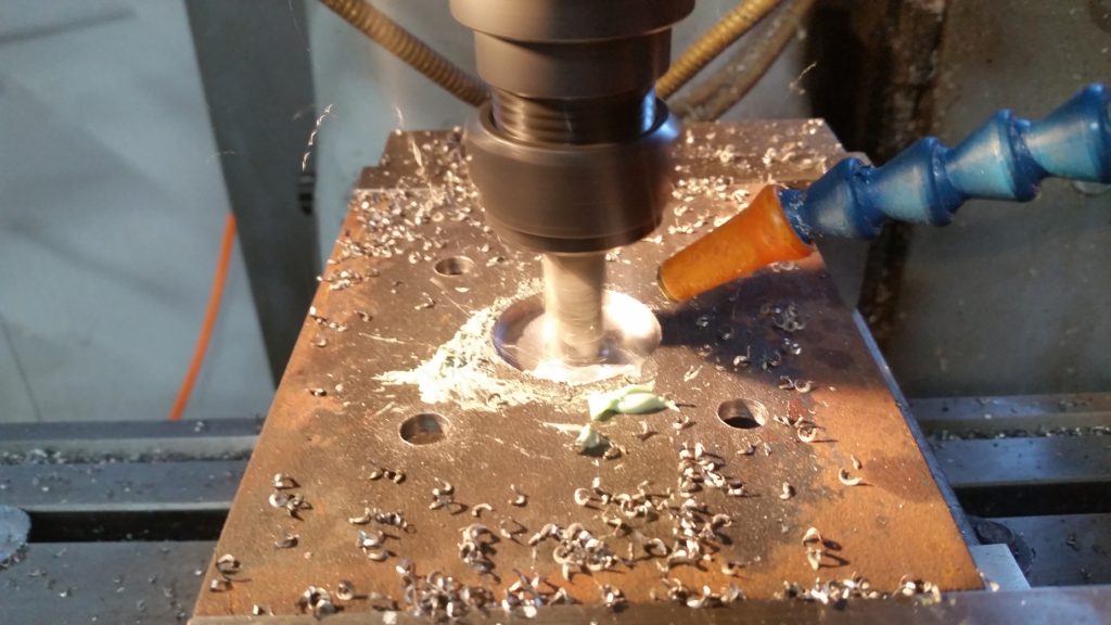
The only thing I really used the CNC milling machine for was making the bearing mount plates, and in fact the machine wasn’t strictly necessary for that. I made two of them using a drill press and a hole saw, but it required too much time and attention and it was faster to set up the milling machine and let it run while I worked on other things. No great degree of precision went into the fabrication; measurements were made with rulers and measuring tape and most holes were drilled by hand.
The 3/16″ and 1/4″ steel plate I used for the bearing and motor mounts was probably overkill and I’m sure lighter steel channel would have been fine. I’d probably have spent more time looking for alternatives if I’d realized how much weight the plate was going to add. At some point I lost count of how many times I’d thought to myself, “Well, what’s another few pounds at this point?”
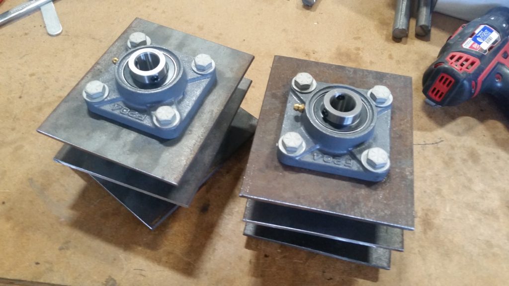
With one reduction stage removed thanks to the gear boxes, I needed twelve bearing mount plates: 2 for each of 4 axles and 2 for the 2 jackshafts.
When I welded the mounts for the axle bearings on to the frame, I set them as low as they’d go – about 1/4″ lower than dead center – for the sake of adding that much more ground clearance. It’s not much, but when your total ground clearance is only 4″, it’s something. I ended up spending way too much time cutting and grinding that excess 1/4″ off the bottom to make sure there wouldn’t be sharp protruding edges. The practice got me comfortable with using angle grinder cutting discs, and made me not feel so bad about skipping the gym.
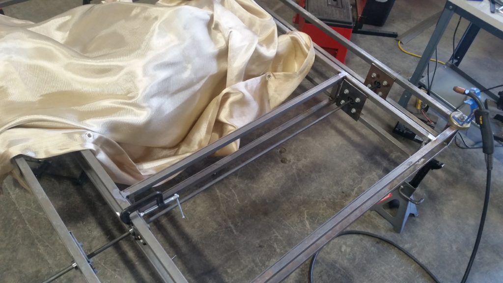
After I accidentally set fire to a shop towel while welding, I decided a welding blanket would be a good idea. It was quickly upgraded from ‘nice to have’ to ‘absolutely essential’ and I’m sure I’d have done a lot more damage without it. MIG welding is fast and fairly easy to learn, but it makes a lot of spatter.
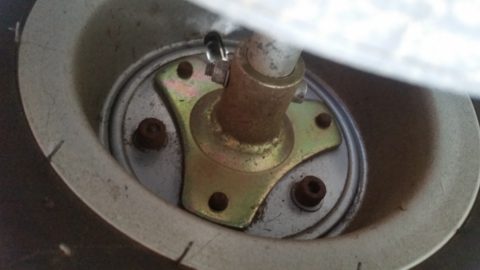
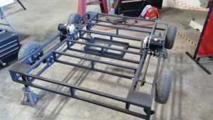
The wheels actually gave me quite a bit of trouble. The ATV had four, obviously, but only two were driven. Those two had live axle hubs – a term I didn’t know when I started, but some ‘build your own go-kart’ sites taught me the basics. These hubs allow the wheels to be connected to an axle that rotates and transmits power to them, as opposed to a dead axle where the axle is fixed and bearings allow the wheels to turn on the axle. A dead axle can be used for drive wheels, too, but it requires a sprocket to be attached to the hub rather than the axle.
The hubs were metric and not terribly sturdy-looking, and no replacements that would fit the bolt pattern seemed to be available. After much hunting I finally realized the easiest way to deal with it was to get rid of the original rims entirely. I bought live axle wheels for about $13 each that mount directly to a 3/4″ keyed shaft.
The hard part was getting the tires on. The rims were intended for tubeless tires, and getting tubed tires on them required a lot of wrestling. I’d recommend not trying to replicate this part if you can avoid it.
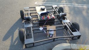
With the wheels mounted, the chassis was finally ready to roll. One of the big unknowns at the start was how much force it was going to take to get rolling on rough terrain. To try to get some kind of real number for that, I took the chassis across the street to an empty lot and hooked it up to a force gauge while my son rode along for extra weight.
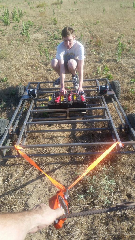
The maximum I measured was about 70 pounds. It wasn’t playa dust and I couldn’t be sure it’d behave the same, but at least I had a number to work with. The spreadsheet I’d made for my torque and speed calculations said I should get about 120 pounds of force at the wheels based on the motors’ rated torque, if my math was right.
Turns out my math was right, but my numbers were wrong – in my favor, thankfully. The torque number I was using was the rated continuous torque. I had it in my head that it was the peak torque. I knew that the stall current would be much higher than the rated continuous current, but it hadn’t occurred to me that the stall torque would also be proportionally higher. Once I got the motors mounted I discovered that not only did a bit of dust not slow it down, but neither did a 200-pound work table. Even with a full load of riders, the acceleration was fast enough that it took a light touch on the controls to not send everyone sprawling.
The big question then was about steering. I’d chosen to use a skid-steer scheme, like a tank or a Bobcat, where one side drives faster than the other to turn in an arc, or each side can be run in opposite directions to spin in place. With the original couch design and its short wheel base that seemed reasonable, but with the longer design I wasn’t sure. I wouldn’t know if it was going to work until I could do some real-world testing.
I came in one Saturday morning to find that my new gear motors were out for delivery. I killed some time organizing my documentation, which turned into an hour of Photoshopping a cover for the documentation binder:
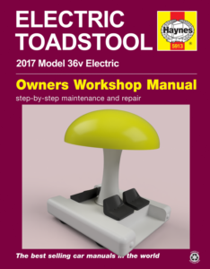
Finally the mailman showed up and put me back on track. 34 days to go at this point.
In the prior few evenings I’d finished welding on the bearing mounts and got the axles, jackshafts, and chains mounted. This new setup would have a 6:1 reduction in the gear box, 1.8:1 to the jackshaft, and 2:1 to the axles. The motors actually came with 11-tooth sprockets instead of the advertised 10-tooth sprockets, which altered the ratios and pushed the maximum speed up a bit past 6 MPH.
By afternoon I had the new motors mounted, and with the motor controller temporarily attached to an aluminum plate for heat dissipation, I took it out for its first test run.
That horrible clicking noise is one of the motor chains slipping. The chain was way too loose, and the 1/8″ plate I’d scrounged up for the new motor mounts was too thin and was bending from the motor’s torque. I had to replace it with 1/4″ plate, after my fourth trip to the steel yard’s remnant pile. The old mounts, no longer where the motors needed to be, stayed on to stiffen the frame since they’d be too hard to cut off. They may someday be motor mounts again, if I switch to 6-wheel drive like I’m planning.
Two days later I had the motor mounts replaced and the chain tension improved, and the security cameras recorded my first actual ride.
Seating was a bit precarious, perched on top of the bare frame. It moved my weight with no trouble, though, and in fact it drove straight over a wheel chock that I’d forgotten to remove. This probably should have been a clue that I shouldn’t have worried so much about whether a bit of dust would keep it from getting started.
The motor controller inexplicably shut down once and thinking that it could be a thermal problem, I got some thermal compound and re-mounted the controller to its heat sink. Less than a minute into testing, the left motor channel went dead, and the right motor got stuck on full. I had to circle around the slowly spinning chassis and grab the battery disconnect switch.
Nathan at Ion Motion Control provided a lot of great support and feedback on the controller throughout the project, and confirmed a few days later that the controller was very dead, with the FETs on the right motor channel totally melted.
It’d be a few says before I could get a new motor controller – this time the much larger MCP266 – so in the meantime, I stripped all of the hardware so I could prime and seal the chassis.
The very knowledgeable sales guy at Custom Colors down the street recommended a good 2-part epoxy primer/sealer. The stuff worked great, but my painting technique needs improvement. It took a lot of fussing to get the paint gun working right, and I made a big sticky mess of the plastic sheets I’d laid down to protect the floor. I had to do some touch-up with a brush, and even then my application was inconsistent. But it doesn’t need to be pretty, just durable.
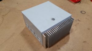
The electronics still needed a place to live, so I got a NEMA 1 enclosure, cut a hole in one wall, and mounted a big surplus heat sink to it that I’d found on eBay.
On August 4, with three weeks to go, I had the new controller installed and ready to test. I set the current limits to 2/3 of the motors’ rated current and everything seemed fine. Acceleration was still enough to knock me off of my temporary plywood seating platform if I wasn’t careful. I gradually increased the current limit to 40 amps with no ill effects. The torque wasn’t needed for straight line acceleration, but turning put a real strain on the motors.
After running back and forth in front of my shop for a few minutes, I took off on a lap of the complex. It was quitting time for most of the neighboring businesses and I probably didn’t ever drive more than a hundred yards without stopping to talk to someone about the project, starting with a couple of technicians at the auto shop on the corner.
I looped back around behind my own shop and somewhere in there I thought I caught a whiff of hot electronics. I stopped to check the motors and controller but nothing felt hot. I decided it was probably the asphalt chewing up my tires on the turns. Skid-steer is not exactly ideal on pavement and I could see that the tread was showing some wear already.
I made it another 50 feet and one of the techs at the diesel injection shop yelled out “What’s it going to be when it grows up?”. It turned out to be one of the guys who had mentored for my son’s high school FRC robotics team. I stopped to talk to him and his coworker and got some pointers on chain tensioning, and as I was about to resume my lap I caught another whiff of something hot. I checked everything again, but couldn’t find anything wrong.
I finished the lap with a climb up the steep driveway at the east end of the parking lot and just as I pulled up in front of the shop I discovered smoke coming from my right motor.
The left motor was quite warm to the touch by now, but the right motor was too hot to hold on to for more than a few seconds.
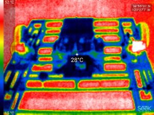
That’s the right motor in white on the right side of the thermogram. The smell was unmistakable at this point.
After the motors had cooled down, I hooked up the laptop to get some current readings from the motor controller. I took it out for a very gentle drive and was discouraged to see both channels frequently maxing out at 40 amps and even with a light load drawing up to 20 amps each.
This really wasn’t looking good. Peukert’s Law says that the usable capacity of a lead-acid battery decreases as the discharge rate increases, and if the car was going to require 40 amps for regular driving, I’d totally drain the batteries in a little over half an hour and probably damage them in the process.
I didn’t get much opportunity to continue my testing that evening. I drove about 50 feet down the parking lot, turned around, and on the drive back realized that my controls weren’t responding. I hit the emergency stop button on the laptop and nothing happened. I reached for the battery disconnect but it was too late and I rammed a curb at about 5 MPH.
The car actually shut itself down when it hit. The motor controller was on a board attached to the chassis with Velcro and the force of the crash sent it flying and yanked the motor quick disconnects apart.
This wasn’t the only time IonStudio tried to kill me. The motor controller should have been accepting commands from the R/C receiver even if it lost communication with the laptop, but that didn’t happen. Multiple times, it simply locked up when the IonStudio software was in use. The MCP266 is apparently part of a fairly new product line, and it got at least three firmware updates over the two months I was building. It’s a great device overall, and I’m hoping they can get the remaining bugs worked out.
I bent the frame more or less back into shape with the help of a bunch of clamps and a sledgehammer, and then put it up on the jack stands for more motor testing.
I hooked up a 100-amp current shunt to get a second opinion on the current draw. I found that the left motor was only drawing about 2 amps with no load, but the right motor was drawing 15. It was undeniably toast. And it was also filling the shop with a horrible smell of burnt insulation.
The 2 amp reading on the left motor was encouraging, though. I found out later that the motor controller’s current measurement reports the peak current over a very short time span and given the pulsed nature of the power it provides to the motor, it can read several times the actual average current draw.
After talking to Shane at Motion Dynamics I decided to order another motor and give it another shot. If it failed again I wouldn’t have time to try something else, and my budget was already shot.
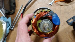
I took the fried motor apart and discovered that one winding was visibly burnt and presumably partly shorted. I think this could be re-wound, but I don’t want to try to tackle that right now and it’s probably not worth the time and expense.
I decided I’d just charge ahead with the rest of the project and hope for the best with the motors. I still didn’t have a real design for the upper part of the frame, but there wasn’t any time to plan out the whole thing in Alibre. I grabbed four leftover 1/4″ steel plates, drilled a couple of holes in each, and mounted them on the corners of the chassis.
Transfer punches are one of those things I didn’t know about when I started learning metalworking, and they’re ridiculously simple and useful. To transfer a hole pattern – in this case I needed to transfer the pattern from the plates to the chassis corners – you could eyeball it and use a center punch or mark it with a marker, but a transfer punch makes it easy if it’s a standard hole size. You just pick a punch of the proper size for the hole, put it in pointy-end first, and hit it with a hammer to leave an indent where the center of the hole goes.
This is nothing Earth-shattering, but it’s a good illustration of the sort of thing that’s easy to miss when you’re starting without a formal education or at least some shop mentoring. It’s for this sort of tidbit that I’ve watched hours of people building things on YouTube. (If only the real world had the ability to be sped up to 1.5x or 2x normal speed like YouTube videos, us ADD sufferers would probably do a lot better in classroom settings.)
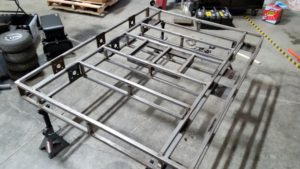
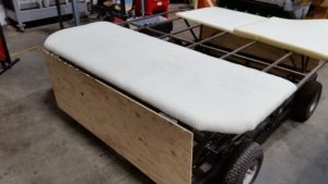
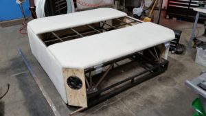
After bolting on the plates, I welded a 3/4″ steel tube upright on to each and put a piece of plywood on top to test the height.
The height seemed good, and the next morning I started on the rest of the frame. I was totally winging it here, with nothing but a rough sketch of the final platform dimensions to go on. I just kept adding steel where it looked like it was needed.
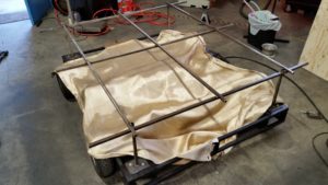
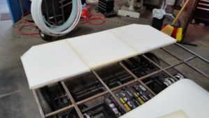
I’d planned to use 1/2″ birch plywood but at the hardware store I decided the cheaper 3/8″ stuff ought to work. Once I got it on the frame I found it was a lot more flexible than I’d like so I added more steel to the frame to compensate.
That’s our shop safety bunny. He keeps people from impaling themselves on sharp protruding objects like this steel tube.
On top of the plywood is a bunch of PVA foam anti-fatigue mats from Harbor Freight. We stopped using them on the floor because they’re death traps when they get a little dusty. They’ll slide right out from under you if you walk too fast. I’d hoped to use them for padding, but they just weren’t soft enough to be useful.
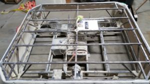
The 3/4″ tubing looked spindly next to the 1″ tubing of the chassis, but again I underestimated its strength. I needed to know that I could trust it, so I climbed up on the center of the frame, the weakest part, and made myself jump, repeatedly. It bounced but nothing broke. The frame would eventually carry more than 2,000 pounds of load without damage, while using only 54 pounds of steel – and much of that was used inefficiently.
On the playa, a welder taking a peek under the hood told me, “There are some good welds in there.” Yes, there are some good welds in there. I would not promise that they’re in the majority. I did my best to make up for it by welding a lot. That included my first overhead MIG welding, which taught me that the backwards baseball cap isn’t a welder’s fashion statement, it’s important protective equipment.
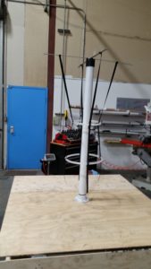
I still needed to figure out the shape and scale of the toadstool itself. I didn’t want it crowding the riders or looking weirdly-proportioned. I’d been planning to make the stem out of a central core with LED rings suspended on tensioned fabric straps or maybe supported by rods radiating from the core. I did a quick prototype of the first idea using long strips of Velcro.
That gave me the chance to try a few sizes and settle on the diameters of the stem’s rings. I wasn’t sure how it’d work with the forces the spandex would be putting on the structure, or if it’d be too wobbly, but at least I had a starting point.
On August 10, I got the replacement motor. It felt a little different, and I ended up swapping its gear motor head for the one that was on the fried motor to get more consistent performance between the two motors. 16 days to go.
At the recommendation of someone in an electric vehicle forum, I upgraded the cooling on the motors. The shaft fans don’t move much air unless the motors are at full speed, so I added 12 volt squirrel cage blowers.
I used 4″ vent covers to make mounting adapters to connect the blowers to the motors. The epoxy on one failed, but some foil duct tape held it together well enough. At least, I thought it was duct tape. It turned out to be RFI shielding tape. About the same thing, only real difference I can see is about an order of magnitude in price. Still not as bad as the time I mistook anisotropic conductive film for masking tape.
The vent covers themselves were a perfect fit. For things like this I’ll often find myself wandering the aisles of the hardware store, from one end to the other. The employees who are nowhere to be found when you actually need them seem to swarm when you’re on one of these “I’ll know it when I see it” quests.
“What are you looking for today?”
“Inspiration.”
I figure about half of the things I buy there get used for something entirely unrelated to their intended purpose. I’ve used random drain/waste/vent fittings in so many projects that I keep a large assortment of them on hand.
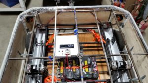
With the new motors and fans mounted, I started working on the controller electronics. The NEMA box needed to be mounted permanently and wires had to be routed in and out of it. This would have been easier if I’d remembered to weld brackets on the chassis before I primed it, but I kludged something together with DIN rails and sheet metal screws.
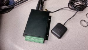
It was about then that my new circuit boards showed up and I put this thing together. It’s a variant of the upcoming WiFi-capable ADS-SR2 repeater controller that incorporates some of the Tracker3 line’s APRS tracking and telemetry with a built-in 1-watt VHF transceiver. It also includes some of the Hyperion hoop code (or rather the 2-channel poi variant of the hoop code) for running LED strips.
If I’d finished it in time, it would have provided a GPS track, web-based telemetry and status information on a tablet or smart phone, and an Art-Net interface to the LEDs for external control. Its most important purpose was really to keep me focused on my actual job during business hours and to harness some of the Burning Man deadline energy. I installed it, made sure I could give it over-the-air firmware updates, and connected it to the motor controller. You could telnet in to it and query the controller manually, but I didn’t have time to finish the rest. I’ll write more about it in a future post when I get more of the functions working.
Now that I had two functioning motors again, I took the car out with its partially-completed deck for a very cautious round of tests. I stopped frequently to check the temperature of the motor housings and of the air coming out of the blowers, but they never got more than slightly warm. Turning was still difficult on anything but slick concrete, but the project was starting to look feasible again.
With a little more work on the plywood parts, it was starting to almost look like a vehicle. I originally had hinges on the front and back panels to provide access to what would have been trunk space, but the hinges proved too difficult to manage with padding and fur so I cut them out and just attached the panels directly to the frame with screws.
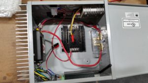
The electronics enclosure wiring wasn’t my best work, but it’s a whole lot better than some of my past hobby projects. The motor controller is visible on the left, attached to the big heat sink, and the two finned devices are DC-DC converters. The black one is a 5 volt converter for the LED lighting and the silver one is a 12 volt converter to power the stereo and the blowers.
I stocked up a while back on assorted colors and gauges of machine tool wire. MTW is more flexible and easier to work with than the typical THHN wire they sell at the hardware store, and hardware stores usually don’t stock more than the colors used in household wiring. I’ve used Radio Shack speaker wire for way too many projects in the past, and MTW was a big improvement.
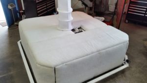
The big chain arts and crafts stores are apparently not the place to shop for upholstery supplies. Our original shop is just down the street and for seven years our next-door neighbor was a small upholstery shop, and I was able to get the foam and batting I needed there for half the price of Jo-Ann’s.
It was a weird feeling pulling into my old parking space. It’s been years, but absolutely nothing has changed. The company logo is still on the front door and the front office’s network cabling is still coiled up in the corner where I left it when we moved out. They’ve apparently never found another renter. It’s like the company molted as it grew and shed its old skin. The upholstery shop, meanwhile, still has the ‘Available’ sign out front that’s been there since at least 2008.
YouTube gave me some pointers on the upholstery. I got this first section done with only eight days to go.
I still didn’t have a way to transport the finished car. I’d designed it so that it could be disassembled into pieces small enough to fit in the sort of box truck our camp usually rented, but truck plans changed and it wasn’t clear that there would be space. I’d need a trailer to haul it.
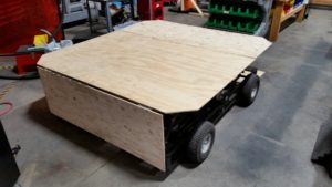
I turned to craigslist looking for any sort of ATV or utility trailer that might be able to fit it. Marginally-suitable trailers seemed to start at about $800, and probably half of them didn’t have plates or proper paperwork. There were plenty of $2000+ flatbed trailers, but I was way over budget on the project already. A little DIY work was going to be necessary if I didn’t want to break the bank, so when a 48″ wide Harbor Freight trailer turned up for $250, I snapped it up.
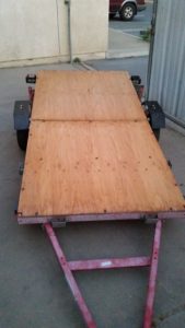
I knew that if it came down to it, I could nail some 2×6’s to the bed to support the car’s frame and simply get a few people to lift the car up and set it on the trailer. Fortunately it didn’t come to that.
The corner panels were on the of the trickier parts of the body. If I’d planned the frame properly, I’d have been able to attach the panels directly to the frame. I ended up attaching them to the side panels using framing angles, and then used zip ties and eye screws to hold down the loose edge and close up the gap. That was my jankiest assembly work on this project, but it held.
The corner panels were also where I mounted the speakers. Art car sound systems can run into the tens of thousands of dollars, but I wasn’t building a big sound car. I just wanted some music for cruising around in deep playa, and for that I spent a grand total of $68 for two pairs of 6.5″ Boss speakers and a cheap car stereo.
Even back when the design included seats, I knew I was going to have to have a place for riders to put their feet. With no seats and riders potentially sitting anywhere, running boards all the way around were a necessity. The car was already much wider than planned so the running boards had to be removable. I hadn’t planned adequately for this, but I made it work.
The sides have 3/4″ supports that slide into the open ends of the 1″ tubing on the chassis. Two bolts on each support hold it in place and keep it from rattling.
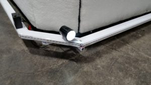
After the running boards were fabricated and painted, and only three days from departure, the car finally got its first LEDs. The running boards were wired as a single strip, driven by a hoop controller with a defective motion sensor that I grabbed off of my workbench. The only setup done on that controller was to delete the pattern folders that were clearly not going to work – like the motion-reactive ones and cartoon characters – and to set the number of LEDs.
I didn’t have the time or budget to order nice protective channels for the LED strips, so I improvised. I used $3 lengths of white shelf rail from Home Depot, flipped upside down. The rails are exactly the right width, they have plenty of places to attach screws, and they survived getting accidentally kicked countless times. The strips were covered over with clear packing tape, which started getting tattered in places after a few days but was easily replaced.
The controller itself was sealed up in heat shrink tubing and zip tied to the corner of the chassis. Final assembly was done on the playa, with no chance to test the whole thing in the shop.
Nine hours later, I had the rest of the LEDs installed, corner panels mounted, stereo working, and most of the upholstery done. I think this was the first time I really felt like it was starting to come together.
Headlights aren’t strictly required for mutant vehicles; you just need to be able to see and be seen. Still, they’re nice to have. I used a pair of cheap LED motorcycle headlights. They worked well, but got kicked around a lot and were held on by duct tape and zip ties by the end of the week.
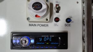
The control panel started as a mock-up and ended up working well enough to stay. It’s a $3 piece of fiberboard set in brackets made from perforated angles, with holes cut by hand using a Dremel tool.
The ‘SCE’ switch got its label before it was assigned a function. It’s a space nerd joke, and a nod to steely-eyed missile man John Aaron. It ended up being the blower control.
Two days before departure, I still hadn’t started on the structure of the toadstool. My prototype might have been made into something usable, but there was too much uncertainty.
After I’d submitted my application in April and started doing more research, I found the Mushroom Patch art car by Butch Kanter. I’m sure I must have seen it on the playa, and it’s possible it planted the idea of a mushroom car in my head, but I’d forgotten about it. After I rediscovered it I got in touch with Butch through Facebook and he shared some information about his mushrooms’ construction.
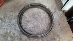
With so little time left, I decided to use his design, modified for my convex cap shape rather than his umbonate shape. I started the day with my fifth trip to the local steel yard, followed by a lot of manual labor with a conduit bender to form rings.
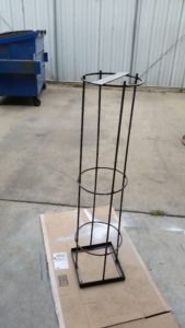
By mid morning I had the stalk structure. I only used three steel rings, since my version would have LEDs in plastic tubes as well and wouldn’t rely only on the steel rings to keep the spandex in its intended shape.
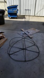
The cap required yet more bending. One arc came out a bit wonky, but it’s supposed to look organic anyway. Getting it perfectly symmetrical with hand-bent steel rod would be nearly impossible, and I didn’t have time to fuss with it.
Mid-afternoon, with the paint drying on the skeleton, I started on the sewing. I’ve got a pretty nice Singer Superb sewing machine in the shop that’s been used for our maker day events and other projects, but I’ve rarely used it myself. This was more than I’d ever sewn with it, and it’d been years since I tried to sew a hem. I’d also never worked with spandex before.
Amazingly, I got it ‘good enough’ on the first try. The stalk portion is just a big tube with a wide hem at the bottom that a ring, slightly larger than the other stalk rings, can fit in. Making the bottom ring the largest makes it easy to pull the spandex up and over the other rings to get access to the inside.
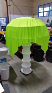
I had no idea how to get the spandex on the cap to come out to a perfect hemisphere shape, so just draped it over the cap, cut off the excess, and sewed a hem to hold the bottom ring.
Until this point, except for some plush mushrooms sewn by friends, this had been entirely a solo project. Now that the toadstool skeleton was done and there was a clear path forward, Julia jumped in and helped with the LEDs. There probably aren’t more than a handful of people in the world with more experience than her and Austin at putting addressable LED strip circuits in 3/4″ plastic tubes, and the shop is certainly well-equipped for it. I’d saved this part for last because it was the part I was most certain I could make work.
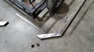
By noon the next day – one day before departure – the upholstery was finished and the toadstool’s mount was complete. It was time to take a break from the car and work on the trailer.
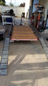
I really wasn’t sure how this was going to turn out, particularly since I was limited to what I had on hand for steel stock, but it worked. I made rails out of 2″ angle and 2″ strip, supported on 1″ square tubing and bolted to the trailer at four points. After it’s loaded, the car is strapped down to the trailer – not the rail assembly – with ratcheting tie-downs, so if the rail assembly breaks, the car should stay on the trailer.
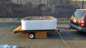
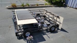
By 6:30, the car was loaded on the trailer and getting a final battery charge. It had no trouble climbing the ramps under its own power.
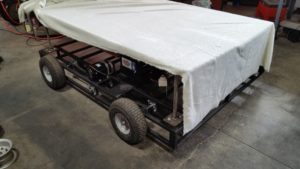
The box truck crew were leaving from San Luis Obispo, 40 minutes to the north, early the next morning. I did all of my final wiring and dust cover installation with the car on the trailer.
The dust covers for the chains were cut from a sheet of corrugated plastic and attached with zip ties. This last-minute work turned out to be a complete waste, as you’ll see in a bit.
At 11:30 PM the night before departure, the car was ready to go. The trailer handled perfectly on the drive up to SLO, and I was back home in time to get about four hours of sleep before returning to the shop.
Normally I aim to be on the road to Burning Man by 10 AM and I take a leisurely, low-traffic route through Nevada with an overnight stop in Fallon where I pick up the last of my supplies. That wasn’t going to happen this time.
The toadstool was finally finished by early afternoon. I’d done almost none of my usual packing and preparation. My checklists – about six pages worth – are what keeps me sane. I didn’t have time for more than a cursory check and had to hope that everything that was supposed to be in the travel trailer was still there.
My son Charlie was riding with me, coming out for his second burn, and we were finally on the road sometime after dinner. There was no stopping overnight this time. We drove straight through and reached the Reno Walmart in time for breakfast. I hadn’t done any grocery shopping yet so that all had to be done there, amidst the other early-arriving burners and employees frantically stocking shelves with water and sunscreen and warning the new hires about the bizarre stampede that was about to begin.
We got water in Gerlach and hit the playa around noon, about the same time we would have if we’d followed our original plan. In fact, we beat the box truck crew by a couple of hours.
There was a minor mishap when I forgot that the trailer needed to be hitched up during unloading. I tried to roll the car off and the trailer tipped. Fortunately nothing was damaged.
Turns out Butch and the Mushroom Patch were camped only a couple of blocks away, and I ran into them several times over the week. Their 2-inch foam padding is something I’m going to have to copy at some point; my 1-inch foam was adequate but I’d be feeling it after a couple of hours of driving.
Cornering performance was about what I expected, and as I expected it was the biggest deficiency. With three people all on the same side, it could still usually perform a zero-radius turn. With more weight or a more evenly distributed load, it had more trouble. With practice I could turn well enough to take corners in the city with four riders, but beyond that it was faster to just kick everyone off when a sharp turn was needed.
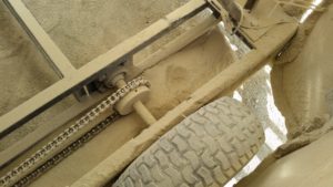
This photo shows why my last-minute dust cover additions were a bad idea. The front edges came loose and nosed into the dust and turned into scoops, piling dust up over the chains. I ripped them out completely.
I had one significant mechanical failure, and that happened while I was in line at the Department of Mutant Vehicles to get my day license. The ride over apparently popped most of the welds between the stalk’s uprights and the 12″ steel rings, and the cap collapsed down one level until it was resting on one of the LED rings, which was just attached by zip ties. It didn’t stop me from getting the license, though.
I probably could have held it together with hose clamps and more zip ties, but I decided to do it right. I drove it across the playa to BRC Welding and Repair, where they graciously let me use their MIG welder to weld the top ring back on. The others I left as they were, which I think added some personality with the toadstool twisting and dancing as the car moved.
I’d fully expected some of the LEDs to fail. They all came from the scrap bin and wouldn’t have been there if they’d been in good shape. Sure enough, a section on the running boards and one of the hoops in the cap failed before I could make it to the DMV for my night license.
The running board section was easy enough, but the hoop was a challenge. Apparently I really overdid it with the conduit bender and my right hand was barely usable. I had to pull the guts of the hoop and splice out sections with a butane soldering iron, and more pieces were failing. I was afraid I’d run out of spares.
I finally got it all working and painstakingly got the guts re-tubed. In the shop, with a standard hoop design, this is routine and only takes a minute. This wasn’t a standard hoop design and I’d planned to bring spare hoops rather than try re-tubing in the field but there hadn’t been time, so there was nothing to do but grin and bear it.
The next trip I made after the DMV was to Rampart to get my hand checked out. The medic doing the assessment heard about my over-exertion on the art car project and asked me what I do for a living. I barely got the word ‘programmer’ out before she was nodding knowingly. Apparently this is a common syndrome on the playa, when techies who spend too much time at a keyboard decide to be welders and sculptors right before the burn.
My hand healed, mostly, and the car held up well the rest of the week. It once lost a key from one of the drive sprockets and was briefly limping along with three-wheel drive, but I had plenty of spares with me. The chain tension was less than ideal and by the end of the week it was sometimes skipping on hard turns, but generally it performed well.
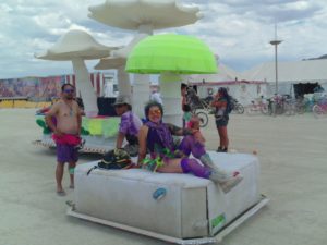
One of its longest cruises was on burn night, where it carried eight people all over the playa. I estimate we returned with at least 1/4 charge remaining, but it’s hard to say.
I made much use of the remote control feature. Almost any time I’d park the car near an art installation, someone would happen by and sit down to rest. I’d wait until a couple of people were on, or until someone looked like they were trying to take a nap, and I’d have the car drive off with them suddenly. With only a single rider, it has surprising acceleration. Deceleration, too. Someone jumped on the car as it was trying to run away. I reversed direction fast and he went rolling, laughing, into the dust.
My remote control range is limited by my ability to see all the way around the car and make sure everyone is safe. I never found out the maximum range of the transmitter.
The car also got some use as a camera dolly for a shot of the owl sculpture by a documentary filmmaker, and later took part in a wedding procession.
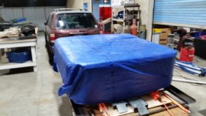
Right after the temple burn it had to be packed up. I re-wrapped and tarped everything, but somehow a rainstorm on the way home still managed to rust the back end of the frame. Cleanup just took a few minutes with an angle grinder, and the frame will get primed and sealed eventually.
The dust was unbelievable. I spent the first hour just trying to blast out the worst of it with the air hose. The whole car had to be stripped down to the last nut and bolt for a proper cleaning and inspection.
The NEMA 1 housing was designed for indoor use and wasn’t sealed. It did much to reduce the volume of dust on the electronics, but for repeated use it could really use better sealing.

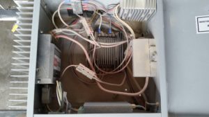
Cleaning the motors required their complete disassembly. I tried for ten minutes or more to blast out the dust from the outside, but it just kept coming. Here, you can see that the windings and armature stack were totally covered with it. I’m a little surprised the reduced airflow didn’t cause any problems. After cleaning and re-assembly, they seem good as new. I figure the gear box grease probably needs to be replaced since it seems to be thoroughly contaminated with dust.
I’ll have it put back together before long, and it looks like no major repairs are needed. I’m likely to be too busy until after Christmas to do any new work on it, but at some point I’ll need to fix the chain tension, redo some of the frame welding to simplify how the sides and corners attach, seal the bare steel, and work on making the toadstool part a little more polished.
Right now the whole car uses about 2,000 addressable LEDs. I’m aiming for 3,000 to 4,000 for next year, with enough density on the toadstool cap for it to be able to display text.